Geometry Tab
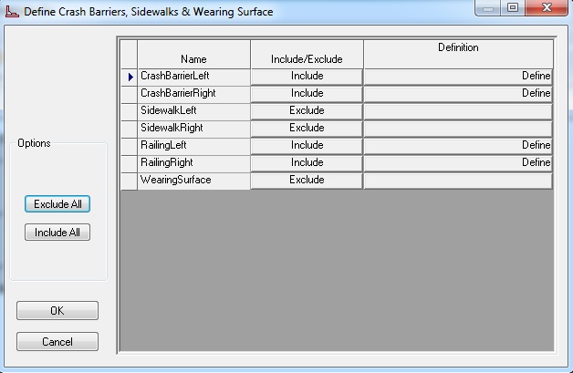
The Geometry tab allows you to input the physical properties of the bridge. Bridge alignments can be described, thus allowing CIP RC/PT Girder to automatically calculate the span lengths along the bridge and girder centerlines. Substructure properties, including pier skews and column spacing, can also be described. This allows the program to calculate varying support-to-support distances across the width of the structure and determines the modified stiffness effects. Superstructure and column cross sections can be entered parametrically, thus providing simplified methods for describing longitudinal variations such as parabolic structure depths, and girder, slab, and column flares. Using this tab, you can create, modify, or delete elements of your bridge description. The weights of crash barriers, footpaths, and wearing surface, if "Included", are automatically added to the Loads/Analysis tab. This information is also used to calculate the carriageway width.

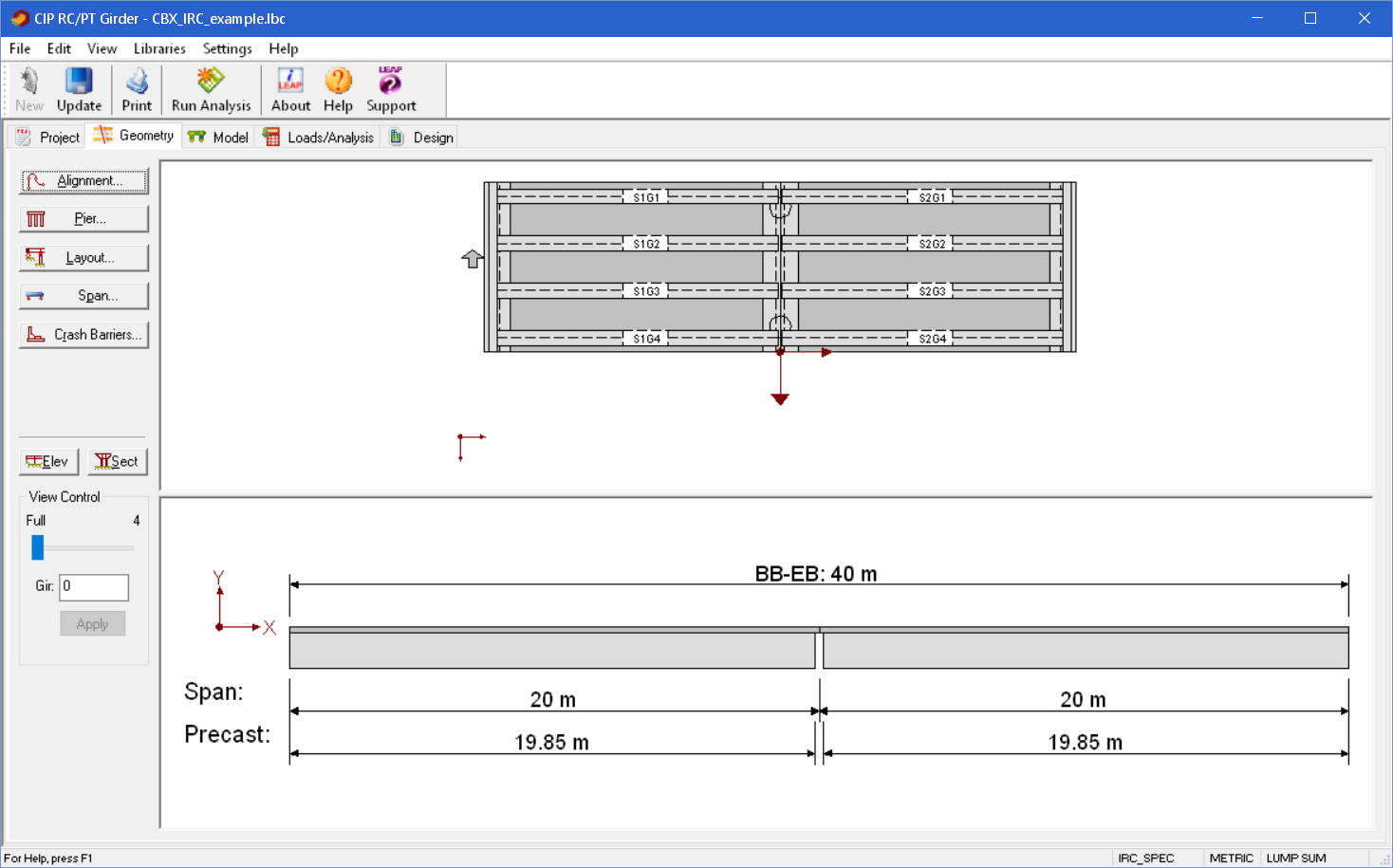

Using the View Control


Adjust the structure's current view location by:
- Selecting the Elevation (Elev) view to display a developed elevation view of the bridge and, if using girder analysis, will also allow you select the elevation along the centerline of each girder.
- Selecting the Section (Sect) view to display the cross section at the specified station.
- Clicking and dragging the slider to define an approximate view location.
- Entering the exact location value and then clicking the Apply button to apply the location value to the view.
Nomenclature
| Setting | Description |
|---|---|
| Alignment | Create and/or modify the bridge alignment using the Bridge Alignment dialog box. |
| Cross Section | Create and/or modify the superstructure cross section using the Cross Section Layout dialog box. |
| Elev | Display the bridge elevation. |
| Layout | Create and/or modify the bridge connections using the Bridge Component Layout dialog box. |
| Pier | Create and/or modify the bridge piers and substructure using the Pier and Column Definitions dialog box. |
| Sect | Display the bridge cross section. |
| View Control | Adjust the current view location by dragging the slider to an approximate view location or entering the exact location value and then clicking the Apply button. |